 |
 |
 |
 |
 |
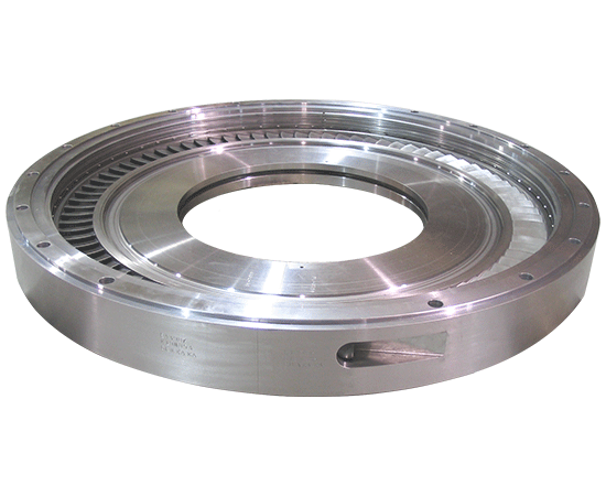
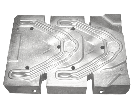
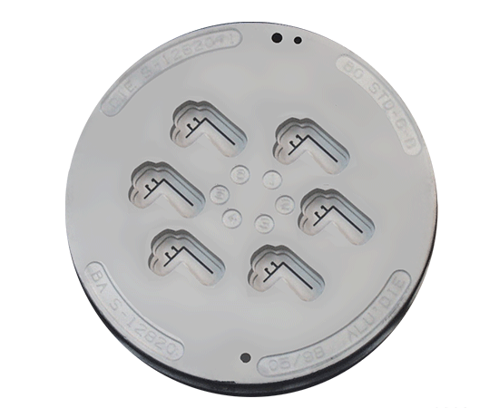
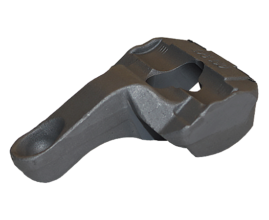
| POWER GENERATOR TURBINE | FORGING DIE | EXTRUSION DIE | AUTOMOTIVE BEARING SUPPORT | 3D-PRINTED NOZZLE |
Menu
NITREG® is a modern heat-treating process, capable of meeting the metallurgical requirements of all nitriding specifications that may have been originally written for salt bath, plasma or traditional gas nitriding. The ability to control the concentration of nitrogen in the surface allows the user to control the growth of the compound layer virtually independently from developing a desirable diffusion zone. This approach facilitates not only meeting any specification requirements, but it also makes it possible to improve on them by allowing tighter tolerances to be satisfied, particularly regarding the thickness and properties of the compound layer.
NITREG® Advantage
Not sure which process or service is right for you?
Contact our global team of heat treat experts and let them guide you or
fill out the contact form to put you in touch with one of our experts!
 |
 |
 |
 |
 |
| POWER GENERATOR TURBINE | FORGING DIE | EXTRUSION DIE | AUTOMOTIVE BEARING SUPPORT | 3D-PRINTED NOZZLE |
Nitriding is a process of diffusing nitrogen atoms into the metal surface. Nitrogen is plentiful on Earth, however, in nature it exists as a two-atom molecule, chemically inert and too large to penetrate the surface. Hence nitriding technologies focus on the source of nascent (atomic) nitrogen.
The main objective of nitriding is to increase the hardness of the component’s surface by enriching it with nitrogen. Regardless of the method, nitriding is a process of diffusing nitrogen into the metal and such diffusion, once individual atoms of nitrogen have penetrated the surface, continues as long as the temperature is high enough, and there is a fresh supply of nascent nitrogen on the surface. In other words, the diffusion is basically the same in all nitriding, while the difference lies in the supply of nitrogen. The latter has a fundamental influence on the resultant properties of the surface.
Generally speaking all ferrous alloys, including stainless steels, cast irons, and even titanium alloys, are capable of being nitrided. However, the various alloys have different characteristics with regard to surface conditions, the natural speed of diffusion and propensity to form nitrides. It is important to understand that even a properly run nitriding process will produce significantly different results on dissimilar materials. Consequently, some users may have insurmountable difficulties, particularly if their methodology is primitive and/or their knowledge and experience inadequate.
| NITRIDING STEELS | ||||
|---|---|---|---|---|
| GRADE AISI | GRADE UNI | MAIN ALLOY COMPONENTS | CORE HARDNESS HV/HRC | SURFACE HARDNESS HV1 |
| N135M | 38CrAlMoA | C=0.38 Cr=1.7 Mo=0.3 Al=1 | 350/36 | 1190-1290 |
| Nitralloy N | C=0.35 Cr=115 Ni=3.5 Mo=0.25 | 350/36 | 1100-1200 | |
| 34CrAlNi7 | C=0.42 Cr=3 Mo=1.2 V=0.20 | 350/36 | 1190-1290 | |
| 42CrMoV12 | 42CrMoV12 | C=0.42 Cr=3 Mo=1.2 V=0.20 | 490 / 48 | 1050-1150 |
| 31CrMo12 | C=0.32 Cr=3 Mo=0.4 | 320 / 32 | 870-920 | |
| 30CrMoV9 | 320 / 32C=0.30 Cr=2.5 Mo=0.2 V=0.15 | 320 / 32 | 900-930 | |
| 25CrMo20 | C=0.25 Cr=6 Mo=0.20 | 280 / 27 | 1000-1100 |
| OTHER HARDENABLE ALLOY STEELS | ||||
|---|---|---|---|---|
| GRADE AISI | GRADE UNI | MAIN ALLOY COMPONENTS | CORE HARDNESS HV/HRC | SURFACE HARDNESS HV1 |
| 4130 | 30CrMo4 | C=0.30 Cr=1 Mo=0.2 | 300 / 30 | 640 – 680 |
| 4140 | 42CrMo4 | C=0.40 Cr=1 Mn=0.9 Mo=0.2 | 300 / 30 | 650 – 700 |
| 4340 | C=0.40 Cr=0.8 Ni=1.8 Mo=0.25 | 310 / 31 | 650 – 700 | |
| 30NiCrMo12 | C=0.30 Cr=0.8 Ni=2.8 Mo=0.12 | 310 / 31 | 600 – 650 | |
| 35NiCrMo15 | C=0.35 Cr=1.7 Ni=3.8 Mo=0.15 | 330 / 33 | 800 – 850 |
| CARBON STEELS | ||||
|---|---|---|---|---|
| GRADE AISI | GRADE UNI | MAIN ALLOY COMPONENTS | CORE HARDNESS HV/HRC | SURFACE HARDNESS HV1 |
| 1010 | C10 | C=0.10 Mn=0.50 | 160 | 320 – 380 |
| 1020 | C20 | C=0.20 Mn=0.50 | 180 | 320 – 380 |
| 1030 | C30 | C=0.30 Mn=0.7 | 180 | 380 – 420 |
| 1045 | C45 | C=0.45 Mn=0.7 | 200 | 420 – 470 |
| 1060 | C60 | C=0.60 Mn=0.7 | 250 / 22 | 525 |
| CARBURIZING ALLOY STEELS | ||||
|---|---|---|---|---|
| GRADE AISI | GRADE UNI | MAIN ALLOY COMPONENTS | CORE HARDNESS HV/HRC | SURFACE HARDNESS HV1 |
| 5115 | 16MnCr5 | C=015 Cr=0.8 Mn=0.9 | 180 | 660 – 720 |
| 20 MnCr5 | C=0.20 Cr=1.15 Mn=1.3 | 240 / 21 | 750 – 800 | |
| 8620 | C=0.20 Cr=0.5 Ni=0.6 Mo=0.2 | 190 | 500 – 520 | |
| 18NiCrMo5 | C=0.18 Cr=0.9 Mn=0.8 Ni=1.3 Mo=0.25 | 210 | 700 – 750 |
| TOOL STEELS | ||||
|---|---|---|---|---|
| GRADE AISI | GRADE UNI | MAIN ALLOY COMPONENTS | CORE HARDNESS HV/HRC | SURFACE HARDNESS HV1 |
| D2 | C=1.5 Cr=12 Mo=1 V=1.1 Co=1 | 580 / 54 | 1270 – 1370 | |
| X150CrMo12 | C=1.5 Cr=12 Mo=0.8 | 580 / 54 | 1270 – 1370 | |
| H13 | AFNOR Z40 | C=0.40 Cr=5.2 Mo=1.5 V=1 | 480 / 48 | 1150 – 1280 |
| X38CrMoV5.1 | C=0.40 Cr=5.2 Mo=1.1 V=0.4 | 480 / 48 | 1180 – 1280 | |
| 40CrMnMo7 | C=0.40 Cr=2 Mn=1.5 Mo=0.2 | 340 / 34 | 870 – 930 | |
| M7 | DIN 1.3348 | C=1 Cr=3.8 Mo=9 W=1.8 V=2 | 787 / 63 | 1100 |
| M42 | DIN 1.3247 | C=1.1 Cr=3.9 Mo=9.5 W=1.5 V=1.1 Co=8. | 865 / 66 | 1100 |
| STAINLESS STEEL | ||||
|---|---|---|---|---|
| GRADE AISI | GRADE UNI | MAIN ALLOY COMPONENTS | CORE HARDNESS HV/HRC | SURFACE HARDNESS HV1 |
| X5CrNiMo18.10 | C=.07 Cr=18 Ni=10 Mo=2 | 230 | 1150 – 1250 | |
| 316L | X2CrNiMo18.10 | C=.03 Cr=18 Ni=12 Mo=2 | 230 | 1150 – 1250 |
| 440B | X90CrMoV18 | C=0.0 Cr=17 Mn=1 Si=1 Mo=0.75 | 420 / 43 | 1000 – 1350 |
| 17-4 PH | C=.07 Cr=16 Mn=1 Si=1 Ni=4 Cu=4 Nb=.3 | 300 / 30 | 950 – 1100 |
A surface exposed to a nitriding medium will generally form two distinct layers. The outside layer is called a compound layer (or white layer) and its thickness generally falls between zero and 0.001” (25 µm). Underneath the white layer we have a diffusion case or diffusion zone. Both together comprise what is generally referred to as the case. However, depending on the material and its original pre-process hardness there will be very significant differences between the properties of these layers.
The images of two Vickers hardness tester indentations shown below illustrate the difference between a controlled and uncontrolled process. The specimen on the left was produced in a traditional process and the cracking of the surface is indicative of the brittleness of the layer. The one on the right is a product of a Nitreg® process where, in spite of the same hardness, cracks have not formed. The Nitreg® treated component is therefore more resilient with high toughness of the compound layer.
Such superior result can only be achieved by controlling the nitrogen concentration in the substrate and the modern approach is control of nitriding potential (KN). Proper understanding and application of the principles that tie nitriding potential (KN), temperature and time are the cornerstone of the Nitreg® technology. An example of our ability to produce a variety of white layer / diffusion case combinations is shown in the following chart, Nitrided case combinations (PDF)
Gradually the ability to control the nitriding potential is becoming a requirement as set forth by specifications such as AMS 2759/10.
In conclusion, Nitreg® is a modern process, capable of meeting the metallurgical requirements of all nitriding specifications that may have been originally written for salt bath, plasma or traditional gas nitriding
| PROPERTIES / FEATURES | NITREG® Controlled Nitriding | Conventional Gas | Salt Bath | Plasma (Ion) |
| Cleaning (Before) | Clean | Clean | Relatively Clean | Very Clean |
| Cleaning (After) | Not required | Not required | Strongly Required | Not Required |
| Heating Time | Short | Short | Very Short | Long |
| Positioning of Parts | Simple | Simple | Simple | Very Complex / Requires Skill & Experience |
| Nitriding of Stainless Steel | Possible | Not Possible | Possible | Possible |
| Operation of Equipment | Very Simple /Fully Automated | Relatively Simple | Simple | Very Complex / Requires Advanced Skills |
| Temperature Control & Uniformity | Excellent | Good | Good | Difficult / Insufficient / Overheat Possible |
| Control of Nitriding Potential | Yes | No | No | No |
| Control of % of ε and γ’ | Possible | No | No | Possible |
| Nitriding with No White Layer | Possible | No | No | Possible |
| Porosity Control | Possible | No | No | Possible |
| Repeatability of Results | Excellent (regardless of load) | Possible (repetitive loads only) | Possible (repetitive loads only) | Possible (repetitive loads only) |
| Equipment Maintenance | Simple | Relatively Complex | Complex | Very Complex |
| Degree of Pollution | Very Low | High | Extremely High | Very low |
| BROCHURE |